10. ECLIC Unit Introduction
10.1. ECLIC Overview
For the real-time or microcontroller applications, the fast interrupt handling scheme is very important, hence, Nuclei processor core have been equipped with an Enhanced Core Local Interrupt Controller (ECLIC), which is optimized based on the RISC-V standard CLIC, to manage all interrupt sources.
Note:
The ECLIC unit only serves one core and is private inside the core, as shown in ECLIC Connection (when ECLIC is enabled).
The ECLIC need to be enabled by setting the LSB bits of CSR registers mtvec as ECLIC mode. Please refer to Setting CLINT or CLIC mode for the details.
The ECLIC is functionally exclusive to PLIC. The ECLIC and PLIC connection diagrams are as described in ECLIC and PLIC Connection Diagram.
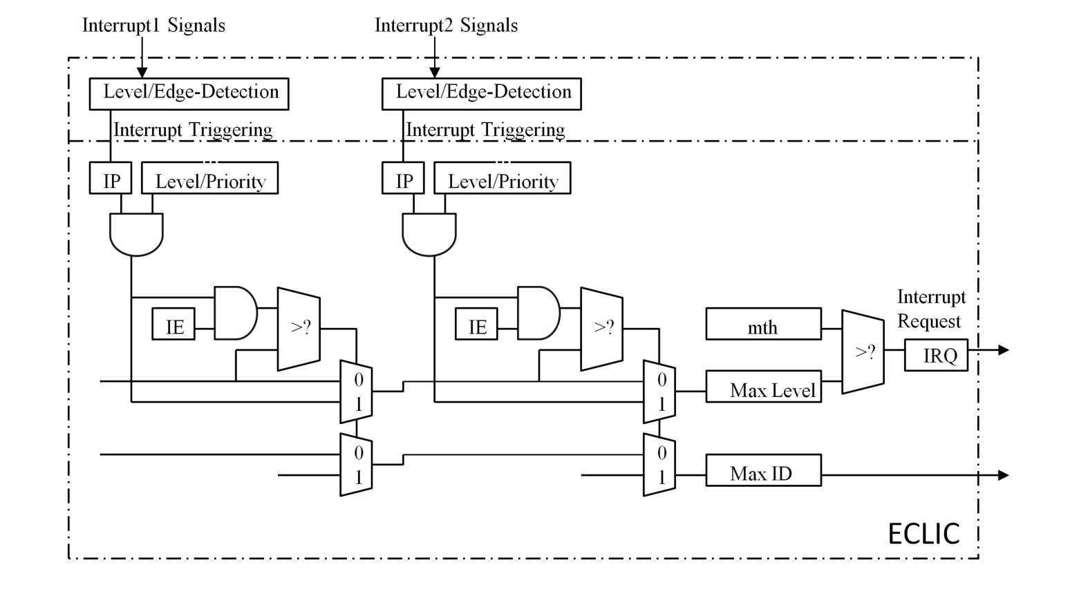
Fig. 10.1 The logic structure of the ECLIC unit
The ECLIC unit is used to arbitrate multiple internal and external interrupts, send interrupt request to core, and support the interrupt preemption. The registers of the ECLIC are described in The address offset of registers in the ECLIC unit, and its structure is shown in The logic structure of the ECLIC unit and the related concepts are as follows:
ECLIC interrupt target
ECLIC interrupt source
ECLIC interrupt source ID
ECLIC registers
ECLIC interrupt enable bits
ECLIC interrupt pending bits
ECLIC interrupt level or edge triggered attribute
ECLIC interrupt level and priority
ECLIC interrupt vectored or non-vectored processing mode
ECLIC interrupt threshold level
ECLIC interrupt arbitration mechanism
ECLIC interrupt response, preemption, tail-chaining mechanism
These will be detailed at next sections.
10.2. ECLIC interrupt target
The ECLIC unit arbitrates the interrupt sources to the processor core (as the interrupt target) by a line as shown in ECLIC Connection (when ECLIC is enabled).
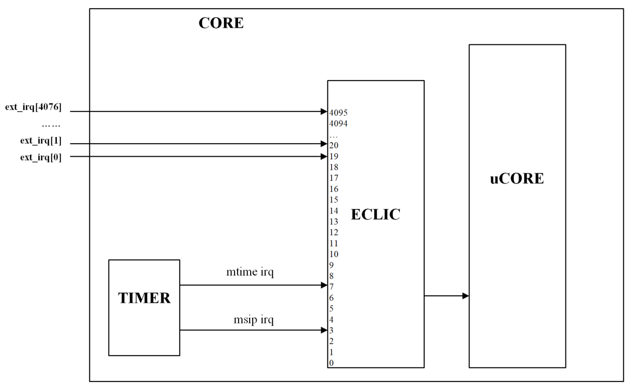
Fig. 10.2 ECLIC Connection (when ECLIC is enabled)
10.3. ECLIC Interrupt Source
As shown in ECLIC Connection (when ECLIC is enabled), the ECLIC unit can support up to 4096 interrupt sources. The ECLIC unit has defined the following concepts for each interrupt source:
ID
IE
IP
Level or Edge-Triggered
Level and Priority
Vector or Non-Vector Mode
These concepts will be detailed at next sections.
10.4. ECLIC Interrupt Source ID
The ECLIC unit has assigned a unique ID to each interrupt source. For example, if a hardware implementation of the ECLIC unit really configured to support 4096 interrupts, then the ID should be 0 to 4095.
Note
In the Nuclei processor core, the interrupt IDs ranged from 0 to 18 are reserved for the core-specified internal interrupts.
The interrupt source ID greater than 18 can be used by the user to connect external interrupt sources.
The details are shown in ECLIC interrupt sources and assignment.
ECLIC interrupt ID |
Function |
Interrupt Source Description |
0 |
Reserved |
This source is not used |
1 |
Reserved |
This source is not used |
2 |
Reserved |
This source is not used |
3 |
Software interrupt |
The software interrupt generated by the TIMER |
4 |
Reserved |
This source is not used |
5 |
Reserved |
This source is not used |
6 |
Reserved |
This source is not used |
7 |
Timer interrupt |
The timer interrupt generated by the TIMER |
8 |
Reserved |
This source is not used |
9 |
Reserved |
This source is not used |
10 |
Reserved |
This source is not used |
11 |
Reserved |
This source is not used |
12 |
Reserved |
This source is not used |
13 |
Reserved |
This source is not used |
14 |
Reserved |
This source is not used |
15 |
Reserved |
This source is not used |
16 |
Reserved |
This source is not used |
17 |
Reserved |
This source is not used |
18 |
Reserved |
This source is not used |
19 ~ 4095 |
External interrupt |
Normal external interrupt defined by users. |
Note
Although the ECLIC unit can support up to 4096 interrupt sources per programming mode, the actual number of supported interrupt sources is indicated in the field clicinfo.NUM_INTERRUPT.
10.5. ECLIC Registers
The ECLIC is a memory-mapped unit.
The base address of the ECLIC unit, please refer to the specific datasheet of the Nuclei processor core.
Registers and the corresponding offset in the ECLIC unit are shown in The address offset of registers in the ECLIC unit.
Offset |
Permission |
Register |
Width |
0x0000 |
RW |
8-bit |
|
0x0004 |
R |
32-bit |
|
0x000b |
RW |
8-bit |
|
0x1000+4*i |
RW |
8-bit |
|
0x1001+4*i |
RW |
8-bit |
|
0x1002+4*i |
RW |
8-bit |
|
0x1003+4*i |
RW |
8-bit |
Note
The above
iindicates the interrupt ID, an interrupt i has its own corresponding clicintip[i], clicintie[i], clicintattr[i], and clicintctl[i] registers.ECLIC registers only support aligned access which is the size of byte, half-word or word.
The above
Rmeans read-only, and any write to this read-only register will be ignored without generating bus error.The ECLIC unit may not be configured to support 4096 interrupt sources. If an index i is not present in the hardware, the corresponding clicintip[i], clicintie[i], clicintctl[i] memory locations appear hardwired to zero.
The address space of ECLIC registers is the range from 0x0000 to 0xFFFF. The value in an address other than the address listed in the above table is constant 0.
These registers are detailed in the next sections.
10.5.1. cliccfg
This cliccfg register is a global configuration register. The software can set global configurations by write this register. cliccfg bit fields describes the bit fields of this register.
Field |
Bits |
Permission |
Default Value |
Description |
Reserved |
7:5 |
R |
N/A |
Reserved, ties to 0. |
nlbits |
4:1 |
RW |
0 |
Used to specified the bit-width of level
and priority in the register clicintctl[i].
Please see ECLIC Interrupt Level and Priority for more details.
|
Reserved |
0 |
R |
N/A |
Reserved, ties to 1. |
10.5.2. clicinfo
The clicinfo register is a global info register. The software can query the global parameters by reading this register. clicinfo bit fields describes the bit fields of this register.
Field |
Bits |
Permission |
Default Value |
Description |
Reserved |
31:25 |
R |
N/A |
Reserved, ties to 0. |
CLICINTCTLBITS |
24:21 |
R |
N/A |
Used to specify the effective bit-width
the register clicintctl[i].
|
VERSION |
20:13 |
R |
N/A |
Hardware implementation version number. |
NUM_INTERRUPT |
12:0 |
R |
N/A |
Number of interrupt sources supported by
the hardware.
|
10.5.3. mth
The mth register is used the set the target interrupt threshold level. The software can set the target interrupt threshold level by writing this register. mth bit fields describes the bit fields of this register.
Field |
Bits |
Permission |
Default Value |
Description |
mth |
7:0 |
RW |
N/A |
10.5.4. clicintip[i]
The clicintip[i] register is the pending flag register for the interrupt source. clicintip[i] bit fields describes the bit fields of this register.
Field |
Bits |
Permission |
Default Value |
Description |
Reserved |
7:1 |
RO |
N/A |
Reserved, ties to 0 |
IP |
0 |
RW |
0 |
10.5.5. clicintie[i]
The clicintie[i] register is the enable bit register for the interrupt source. clicintie[i] bit fields describes the bit fields of this register.
Field |
Bits |
Permission |
Default Value |
Description |
Reserved |
7:1 |
R |
N/A |
Reserved, ties to 0. |
IE |
0 |
RW |
0 |
10.5.6. clicintattr[i]
The clicintattr[i] register is used to indicate the attribute of the interrupt source. The software can set the attribute of the interrupt source by writing this register. clicintattr[i] bit fields describes the bit fields of this register.
Field |
Bits |
Permission |
Default
Value
|
Description |
Reserved |
7:6 |
R |
N/A |
Reserved, ties to 2’b11 |
Reserved |
5:3 |
R |
N/A |
Reserved, ties to 0 |
trig |
2:1 |
RW |
0 |
Used to set the level or edge triggered attribute of the interrupt source.
See ECLIC Interrupt Source Level or Edge-Triggered Attribute for more details.
|
shv |
0 |
RW |
0 |
Used to set whether the interrupt is vectored or non-vectored.
See ECLIC Interrupt Vectored and Non-Vectored Processing Mode for more details.
|
10.5.7. clicintctl[i]
The clicintctl[i] register is the control register of the interrupt source. The software can set the level and priority by writing this register. The level and priority field are dynamically allocated based on the value of cliccfg.nlbits. Please see ECLIC Interrupt Level and Priority for more details.
10.6. ECLIC Interrupt Enable Bit (IE)
As shown in The logic structure of the ECLIC unit, the ECLIC unit has allocated an interrupt enable bit (IE) for each interrupt source which is the field clicintie[i].IE whose function are the follows:
The clicintie[i] register of each interrupt source is a both readable and writeable memory-mapped register. Hence the software can program it.
If the clicintie[i] register is programmed to 0, it means that this interrupt source is masked.
If the clicintie[i] register is programmed to 1, it means that this interrupt is enabled.
10.7. ECLIC Interrupt Pending Bit (IP)
As shown in The logic structure of the ECLIC unit, the ECLIC unit has allocated an interrupt pending bit (IP) for each interrupt source which is the field clicintip[i].IP whose function are the follows:
If the IP bit of one interrupt source is 1, it means this interrupt is triggered. The trigger condition of the interrupt source depends on whether this interrupt is level-triggered or edge-triggered as described in ECLIC Interrupt Source Level or Edge-Triggered Attribute.
The IP bit of the interrupt source is both readable and writeable. The behavior of the software writing IP bits depends on whether the interrupt source is level or edge triggered. Please see ECLIC Interrupt Source Level or Edge-Triggered Attribute for more details.
For edge-triggered interrupt source, the IP bit may be cleared by the hardware itself. Please see ECLIC Interrupt Source Level or Edge-Triggered Attribute for more details.
10.8. ECLIC Interrupt Source Level or Edge-Triggered Attribute
As shown in The logic structure of the ECLIC unit, each ECLIC interrupt source can be set as level triggered or edge triggered by setting the value of clicintattr[i].trig. The key points are the followings:
When clicintattr[i].trig[0] == 0, this interrupt source is set as a level-triggered interrupt.
If the interrupt source is set as level-triggered, the IP bit of the interrupt source will reflect the level of the interrupt source in real time.
If the interrupt source is set as level-triggered, the IP bit reflects the level of the interrupt in real time, so software writes to this IP bit is ignored, that is, the software cannot set or clear the IP bit by writing operation. If the software needs to clear the interrupt pending bit, it can only be done by clearing the original source of the interrupt.
When clicintattr[i].trig[0] == 1 and clicintattr[i].trig[1] == 0, this interrupt source is set as a rising edge-triggered interrupt:
If the interrupt source is set as rising edge-triggered, when the ECLIC detects the rising edge of the interrupt source, the interrupt source is triggered in the ECLIC, and the IP bit of the interrupt source is asserted.
If the interrupt source is set as rising edge-triggered, the IP bit is writeable for the software, which means the software can set or clear the IP bit by writing operations.
Note
For rising edge-triggered interrupt, in order to improve the efficiency of the interrupt processing, when the interrupt is taken and the core jumps to the ISR (Interrupt Service Routine), the hardware of the ECLIC will clear the IP bit automatically, and the software needs not to clear the IP bit in ISR.
When clicintattr[i].trig[0] == 1 and clicintattr[i].trig[1] == 1, this interrupt source is set as a falling edge-triggered interrupt:
If the interrupt source is set as falling edge-triggered, when the ECLIC detects the falling edge of the interrupt source, the interrupt source is triggered in the ECLIC, and the IP bit of the interrupt source is asserted.
If the interrupt source is configured as falling edge-triggered, the IP bit is writeable for the software, which means the software can set or clear the IP bit by writing operations
Note
For rising edge-triggered interrupt, in order to improve the efficiency of the interrupt processing, when the interrupt is taken and the core jumps to the ISR (Interrupt Service Routine), the hardware of the ECLIC will clear the IP bit automatically, and the software needs not to clear the IP bit in ISR.
10.9. ECLIC Interrupt Level and Priority
As shown in The logic structure of the ECLIC unit, each interrupt sources of the ECLIC can be configured with specified level and priority, and the key points are the followings:
The register clicintctl[i] of each interrupt source is 8-bit width theoretically, and effective bits actually implemented by the hardware are specified by the CLICINTCTLBITS in the register clicinfo. For example, if the value of the clicinfo.CLICINTCTLBITS field is 6, it means that only the upper 6-bit of the clicintctl[i] register are true valid bits, and the lowest 2 bits are tied to 1, as shown in clicintctl[i] format example.
Note
The field CLICINTCTLBITS is a readable constant value, and the software cannot overwrite it. The theoretically reasonable value range of it is 2 <= CLICINTCTLBITS <= 8. The actual value is determined by the specified hardware implementation. Please refer to the specific datasheet of the Nuclei processor core.
The effective bits of clicintctl[i] register have two dynamic fields, which are used to specify the level and the priority of the interrupt source. The width of the level filed is defined by field nlbits in cliccfg. For example, if the value of cliccfg.nlbits is 4, it means that the upper 4-bit of the effective bits in clicintctl[i] is the level field while the other lower effective bits is the priority field, as shown in the example in clicintctl[i] format example.
Note
The field cliccfg.nlbits is both readable and writeable, which means the software can change its value.
![clicintctl[i] format example](../_images/image027.png)
Fig. 10.3 clicintctl[i] format example
The key points of interrupt level are the followings:
The value of level is read in a left-aligned manner. Except the effective bits (defined by the value of cliccfg.nlbits), the low ineffective bits are all filled with the constant 1, as shown in the example in Example for the decoding of level.
Note
If cliccfg.nlbits > clicinfo.CLICINTCTLBITS, it means that the number of bits indicated by nlbits exceeds the effective bits of the clicintctl[i] register, and the excess bits are all filled with the constant 1.
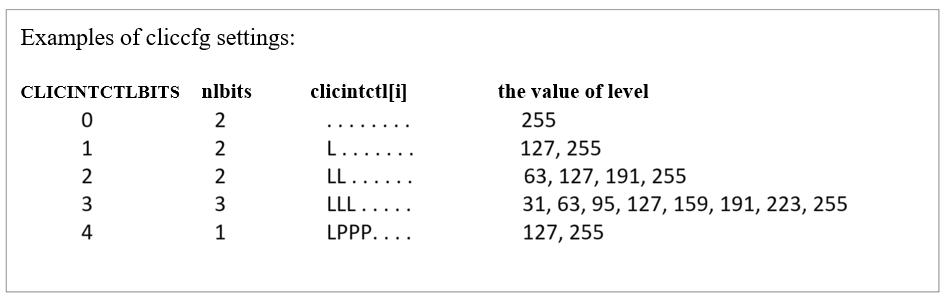
If cliccfg.nlbits = 0, the value of level will be regarded as a fixed value 255. As shown in Examples of eclic_reg_cliccfg settings.
The greater value of level, the higher priority.
Note
Higher-level interrupts can preempt lower-level interrupts, which is called as interrupt preemption, as detailed in (CLIC mode) Interrupt Preemption
If there are multiple pending interrupts (IP is 1), then the ECLIC needs to make an arbitration to determine which interrupt needs to be sent to the core to take. The arbitration needs to take the level of each interrupt source into the consideration. Please see Interrupt Levels, Priorities and Arbitration for details.

Fig. 10.4 Example for the decoding of level
The key points of the interrupt priority are the follows:
The value of priority is also read in a left-aligned manner. Except the effective bits (clicinfo.CLICINTCTLBITS - cliccfg.nlbits), the low ineffective bits are all filled with the constant 1.
The greater the value of the priority, the higher priority, note:
The priority of the interrupt does not participate in the judgment of the interrupt preemption, which means whether the interrupt can be preempted or not has nothing to do with the value of the priority of the interrupt.
When multiple interrupts are simultaneously pending, the ECLIC needs to make an arbitration to determine which interrupt is sent to the core to handle. The arbitration needs to refer to the value of level/priority of each interrupt source. Please see ECLIC Interrupt Arbitration Mechanism for details.
10.10. ECLIC Interrupt Vectored and Non-Vectored Processing Mode
Each interrupt source of the ECLIC can be set to vectored or non-vectored (via the shv field of the register clicintattr[i]). The key points are the followings:
If the interrupt is set as vectored, the core will directly jump to the target address stored in the vector table entry when the interrupt is taken. For a detailed description of the interrupt vectored processing mode, please see Vectored Processing Mode.
If the interrupt is set as non-vectored, the core will jump to the common base entry shared by all interrupts when the interrupt is taken. For a detailed description of the interrupt non-vectored processing mode, please see Non-Vectored Processing Mode.
10.11. ECLIC Interrupt Threshold Level
As shown in The logic structure of the ECLIC unit, the ECLIC can set the threshold level (mth) of a specific interrupt threshold level. The key points are as follows:
The mth register is an 8-bit register, all bits are readable and writable, and the software can write this register to set the threshold. Note: this threshold indicates a level value.
Only when the level of the interrupt finally arbitrated by the ECLIC is higher than the value in the mth register, the interrupt can be sent to the processor core.
10.12. ECLIC Interrupt Arbitration Mechanism
The principles for the ECLIC to arbitrate all of its interrupt sources are as follows:
Only interrupt sources that meet all of the following conditions can participate in the arbitration:
The enable bit (clicintie[i]) of the interrupt source must be 1.
The pending bit (clicintip[i]) of the interrupt source must be 1.
The rules for the arbitration among all participated interrupt sources are:
First, check the level, the larger the level value of the interrupt source, the higher the arbitration priority.
If the level is equal, then check the priority, the interrupt source that has greater value of priority will have higher arbitration priority.
If both level and priority are equal, then the ID is taken into the consideration. The interrupt source with the larger interrupt ID has higher arbitration priority.
If the level value of the interrupt source that wins the arbitration has a greater value than the level value in mth, then the interrupt request signal to the core will be asserted.
10.13. ECLIC Interrupt Taken, Preemption and Tail-Chaining
After the ECLIC interrupt request is sent to the processor core, the core will respond to it. Through the coordination by the ECLIC and the core, the operation of interrupt preemption and tail-chaining are supported. Please see (CLIC mode) Interrupt Preemption, (CLIC mode) Interrupt Tail-Chaining, and (CLIC mode) Vectored and Non-Vectored Processing Mode of Interrupts for more details.