4.1.1.5. Core feature: Vectored Interrupt
Purpose
To get familiar with the vectored processing mode of interrupt in Nuclei N Class Processors
To know the difference between non-vectored interrupt and vectored interrupt
To know how to implement nesting of vectored interrupt
Requirements
The following hardware and source codes are required:
PC host
Nuclei board (RV-STAR Development Board)
USB Type-C cable
nuclei-sdk/board-labs/rvstar/nesting_of_interrupts
Content
Through learning the Chapter 6 of Nuclei RISCV ISA Spec and Interrupt and Exception Handling File in NMSIS to get familar with vectored processing mode of interrupt in Nuclei N Class Processors.
Programming the EXTI peripheral registers and the Timer peripheral registers of SoC, ECLIC registers of Core to create three external interrupts which are triggered by pressing the on-board user key, SoC Timer1 and SoC Timer2 seperately.
Set interrupt initiated by user key to the highest level and non-vectored processing mode
Set interrupt initiated by SoC Timer2 to the middle level and vectored processing mode, and not support interrupt preemption
Set interrupt initiated by SoC Timer1 to the lowest level and vectored processing mode, and support interrupt preemption
These three interrupt service routines change on-board RGB LED to three different statuses.
Note
About the detailed principles of interrupt preemption, please refer to Core feature: Nesting of Interrupts
Principles
For an interrupt service routine of a vectored interrupt, the indication __attribute__ ((interrupt)) is required to indicate compiler this C function is an interrupt service routine, as the figure below shown. __attribute__ ((interrupt)) is defined as __INTERRUPT in NMSIS, see the example in appendix.
Note
Explanation:
In the vector processing mode, since the core does not save the context before jumping to the interrupt service routine, theoretically the interrupt handler cannot call any sub-function which means the handler must be a leaf function.
As long as the __attribute__ ((interrupt)) is used to indicate this function is an interrupt handler, the compiler will automatically detect whether this function calls any sub-function. If it calls any sub-function, the compiler will automatically insert a piece of code to save the context.
For an interrupt service routine of a vectored interrupt which needs to support interrupt preemption, it should save related CSR registers and enable global interrupt in the beginning, and disable global interrupt and restore related CSR registers in the ending, as the figure below shown. These opreations are defined as SAVE_IRQ_CSR_CONTEXT() and RESTORE_IRQ_CSR_CONTEXT() in NMSIS, see the example in appendix.
Note
Explanation: If the interrupt is set to vectored processing mode, once it’s taken, the processor core will jump to the target address saved in the Vector Table Entry directly, which is the corresponding interrupt service routine of the interrupt. The processor core doesn’t perform any special operation before jumping to the interrupt service routine, and the value of mstatus.MIE is updated to 0 by the hardware, which means the interrupt is global disabled and no new interrupt will be taken once the core is handling the interrupt.
For non-vectored interrupt, it support interrupt preemption by default, so its interrupt service routine does not need __INTERRUPT , SAVE_IRQ_CSR_CONTEXT() and RESTORE_IRQ_CSR_CONTEXT() these operations. About the detailed processing flow and description, refer to Core feature: Interrupt and Core feature: Nesting of Interrupts.
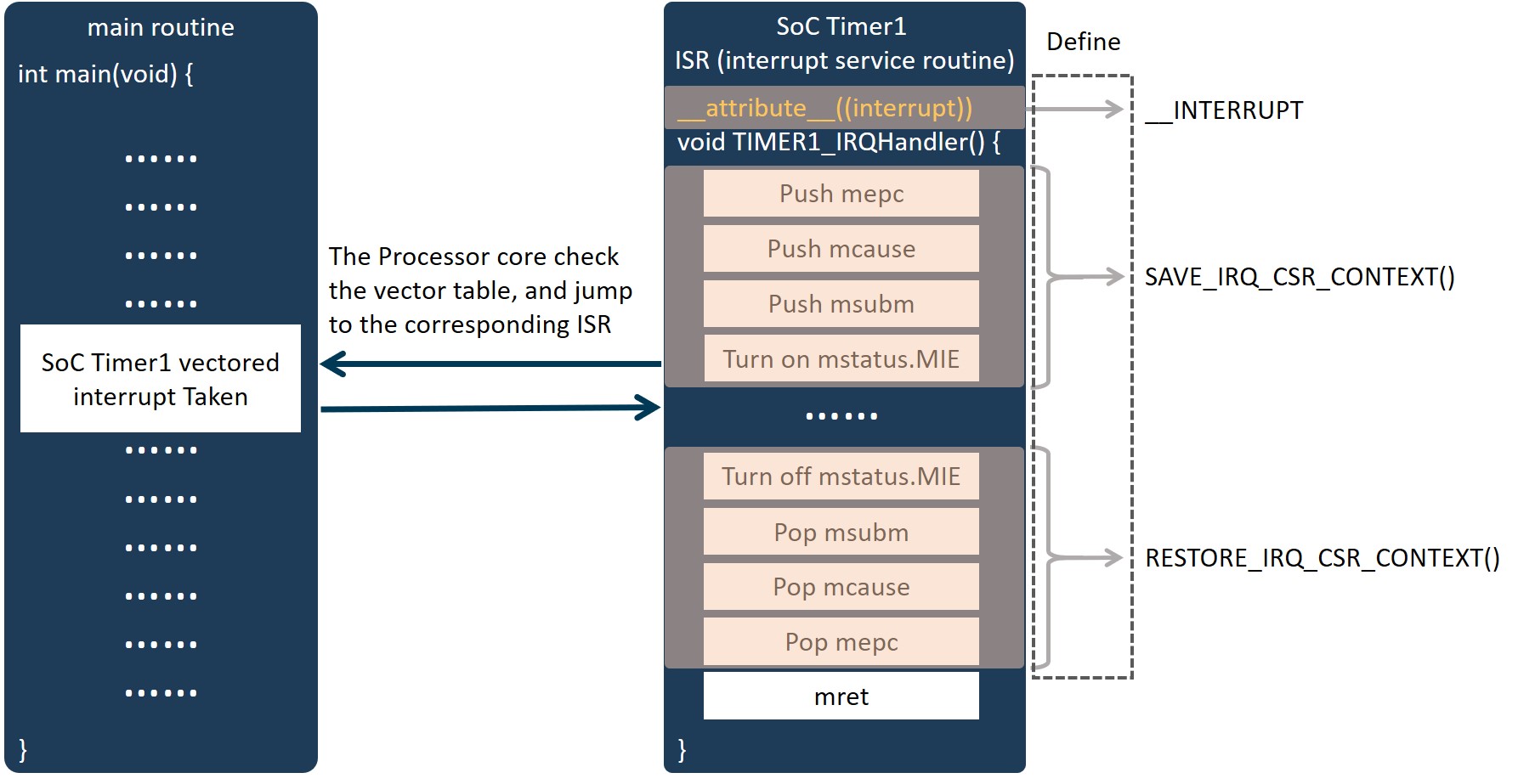
Fig. 4.21 Example for vectored interrupt supported preemption
In Nuclei SDK, gd32vf103_rvstar.h provides API to operate the on-board peripherals, gd32vf103_timer.h provides API to operate the SoC Timer, gd32vf103_exti.h provides API to operate the SoC EXTI, core_feature_eclic.h provides API to config ECLIC feature for Nuclei Core.
The code for this lab is located in nuclei-sdk/board-labs/rvstar/vectored_interrupt. You can see it in the appendix.
It can be divided into 7 parts:
Part1 : Board config, initialize on-board RGB LED and user key
Part2 : Timer config, set working mode of TIMER1 and TIMER2, enable Timer update interrupt in SoC level for them.
Part3 : EXTI config, set PA0 to used as EXTI source and enable EXTI interrupt in SoC level
Part4 : ECLIC config, interrupt config in Processor level for each interrupt sources (interrupt enable, level and priority, non-vectored or vectored)
Part5 : EXTI interrupt service routine, change the status of on-board RGB LED (set color to White)
Part6 : SoC Timer1 interrupt service routine, change the status of on-board RGB LED (set color to Green)
Part7 : SoC Timer2 interrupt service routine, change the status of on-board RGB LED (set color to Blue)
The program flow is shown below:

Fig. 4.22 Programming flow of interrupt preemption
Steps
Connect RV-STAR Development Board and your computer with the USB Type-C cable.

Fig. 4.23 Connect with PC
Note
When connect your board with the PC, just keep the on-board jumpers as default. About on-board jumpers’ function, please refer to Jumper Section.
Compile and run the
nuclei-sdk/board-labs/rvstar/vectored_interruptexample. About the develop environment, you can choose Nuclei SDK or Segger Embedded Studio.
Nuclei SDK
Using the following commands:
cd /nuclei-sdk/board-labs/rvstar/vectored_interrupt
make SOC=gd32vf103 BOARD=gd32vf103v_rvstar upload
Note
About the acquisition of source codes, please refer to Software Source Codes.
About the detailed usage of Nuclei SDK, please refer to How to develop with Nuclei SDK.
Segger Embedded Studio
Using the following actions:

Fig. 4.24 Operations in Embedded Studio
Note
About the acquisition of Segger Embedded Studio solutions, please refer to Software Source Codes.
About the detailed usage of Segger Embedded Studio, please refer to How to develop with Segger Embedded Studio.
Check the status of on-board RGB LED, then press the on-board User Key(PA0-WKUP), and check the status of on-board RGB LED again.
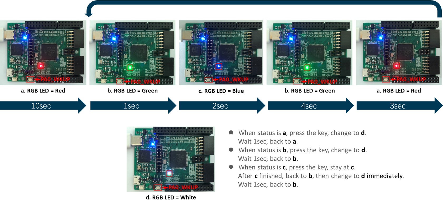
Fig. 4.25 Experimental results
Exercises
Try to create you own application which test the differences between the non-vectored and vectored processing mode of interrupt.
Appendix
rvstar/vectored_interrupt/main.c
/**
    \brief      main function
    \param[in]  none
    \param[out] none
    \retval     none
  */
int main(void)
{
    uint8_t timer1_intlevel=1;
    uint8_t timer2_intlevel=2;
    uint8_t exti_intlevel  =3;
    int32_t returnCode;

    /* Board Config */
    gd_rvstar_led_init(LED3);
    gd_rvstar_led_init(LED1);
    gd_rvstar_led_init(LED2);

    gd_rvstar_key_init(WAKEUP_KEY_GPIO_PORT,KEY_MODE_EXTI);

    /* Timer Config */
    soc_timer_config();

    /* EXIT config */
    user_key_exti_config();

    /* ECLIC config */
    returnCode = ECLIC_Register_IRQ(EXTI0_IRQn, ECLIC_NON_VECTOR_INTERRUPT,
                    ECLIC_LEVEL_TRIGGER, exti_intlevel, 0, NULL);
    returnCode = ECLIC_Register_IRQ(TIMER2_IRQn, ECLIC_VECTOR_INTERRUPT,
                    ECLIC_LEVEL_TRIGGER, timer2_intlevel, 0, NULL);
    returnCode = ECLIC_Register_IRQ(TIMER1_IRQn, ECLIC_VECTOR_INTERRUPT,
                    ECLIC_LEVEL_TRIGGER, timer1_intlevel, 0, NULL);

    /* Enable interrupts in general */
    __enable_irq();

    /* Timer Start */
    timer_enable(TIMER1);
    delay_1ms(1000);
    timer_enable(TIMER2);

    /* RGB Control */
    while(1)
    {
      /* set led to RED */
      gd_rvstar_led_off(LED2);
      gd_rvstar_led_off(LED1);
      gd_rvstar_led_on(LED3);
    }

    return 0;
}


/**
    \brief      configure the TIMER peripheral
    \param[in]  none
    \param[out] none
    \retval     none
  */
void soc_timer_config()
{
    timer_parameter_struct timer_initpara;

    /* ----------------------------------------------------------------------------
    TIMER1 Configuration:
    TIMER1CLK = SystemCoreClock/54000 = 2KHz.
    TIMER1CAR = 20000
    ---------------------------------------------------------------------------- */
    rcu_periph_clock_enable(RCU_TIMER1);

    timer_deinit(TIMER1);

    timer_update_source_config(TIMER1, TIMER_UPDATE_SRC_REGULAR);

    /* initialize TIMER init parameter struct */
    timer_struct_para_init(&timer_initpara);
    /* TIMER1 configuration */
    timer_initpara.prescaler         = 53999;
    timer_initpara.alignedmode       = TIMER_COUNTER_EDGE;
    timer_initpara.counterdirection  = TIMER_COUNTER_UP;
    timer_initpara.period            = 20000;
    timer_initpara.clockdivision     = TIMER_CKDIV_DIV1;
    timer_init(TIMER1, &timer_initpara);

    timer_interrupt_enable(TIMER1, TIMER_INT_UP);

    /* ----------------------------------------------------------------------------
    TIMER2 Configuration:
    TIMER2CLK = SystemCoreClock/54000 = 2KHz.
    TIMER2CAR = 20000
    ---------------------------------------------------------------------------- */
    rcu_periph_clock_enable(RCU_TIMER2);

    timer_deinit(TIMER2);

    timer_update_source_config(TIMER2, TIMER_UPDATE_SRC_REGULAR);

    /* TIMER2 configuration */
    timer_init(TIMER2, &timer_initpara);

    timer_interrupt_enable(TIMER2, TIMER_INT_UP);
}


/**
    \brief      configure the EXTI peripheral for user key
    \param[in]  none
    \param[out] none
    \retval     none
  */
void user_key_exti_config()
{
    /* enable the AF clock */
    rcu_periph_clock_enable(RCU_AF);

    /* connect EXTI line to key GPIO pin */
    gpio_exti_source_select(WAKEUP_KEY_EXTI_PORT_SOURCE, WAKEUP_KEY_EXTI_PIN_SOURCE);

    /* configure key EXTI line */
    exti_init(EXTI_0, EXTI_INTERRUPT, EXTI_TRIG_FALLING);
    exti_interrupt_flag_clear(EXTI_0);
}

/**
    \brief      EXTI line0 interrupt service routine
    \param[in]  none
    \param[out] none
    \retval     none
  */
void EXTI0_IRQHandler()
{

    if (SET == exti_interrupt_flag_get(WAKEUP_KEY_PIN)){

        if(RESET == gd_rvstar_key_state_get(KEY_WAKEUP)){

            /* clear EXTI lines interrupt flag */
            exti_interrupt_flag_clear(WAKEUP_KEY_PIN);

            /* set led to White */
            gd_rvstar_led_on(LED3);
            gd_rvstar_led_on(LED2);
            gd_rvstar_led_on(LED1);

            delay_1ms(1000);
        }
    }

}

/**
    \brief      TIMER1 interrupt service routine
    \param[in]  none
    \param[out] none
    \retval     none
  */
__INTERRUPT void TIMER1_IRQHandler()
{
    uint16_t cnt;

    // save CSR context
    SAVE_IRQ_CSR_CONTEXT();

    if(SET == timer_interrupt_flag_get(TIMER1, TIMER_INT_FLAG_UP)){
      /* clear update interrupt bit */
      timer_interrupt_flag_clear(TIMER1, TIMER_INT_FLAG_UP);

      for(cnt = 0; cnt < 5; cnt++)
      {
          /* set led to GREEN */
          gd_rvstar_led_off(LED3);
          gd_rvstar_led_off(LED2);
          gd_rvstar_led_on(LED1);
          delay_1ms(1000);
      }
    }

    // restore CSR context
    RESTORE_IRQ_CSR_CONTEXT();
}


/**
    \brief      TIMER2 interrupt service routine
    \param[in]  none
    \param[out] none
    \retval     none
  */
__INTERRUPT void TIMER2_IRQHandler()
{
    if(SET == timer_interrupt_flag_get(TIMER2, TIMER_INT_FLAG_UP)){
        /* clear update interrupt bit */
        timer_interrupt_flag_clear(TIMER2, TIMER_INT_FLAG_UP);

        /* set led to BLUE */
        gd_rvstar_led_off(LED3);
        gd_rvstar_led_off(LED1);
        gd_rvstar_led_on(LED2);
        delay_1ms(2000);
    }
}