2. Supported Hardware Platform
The following Nuclei Processor Cores based hardware platforms (more boards will be added in the future) are supported in this handbook.
2.1. RV-STAR Development Board
RV-STAR is a RISC-V development board based on GD32VF103 MCU. It provides on-board debugger, reset and wake-up user keys, RGB LED, USB OTG, and EXMC, Arduino, PMOD extension interfaces and other resources.
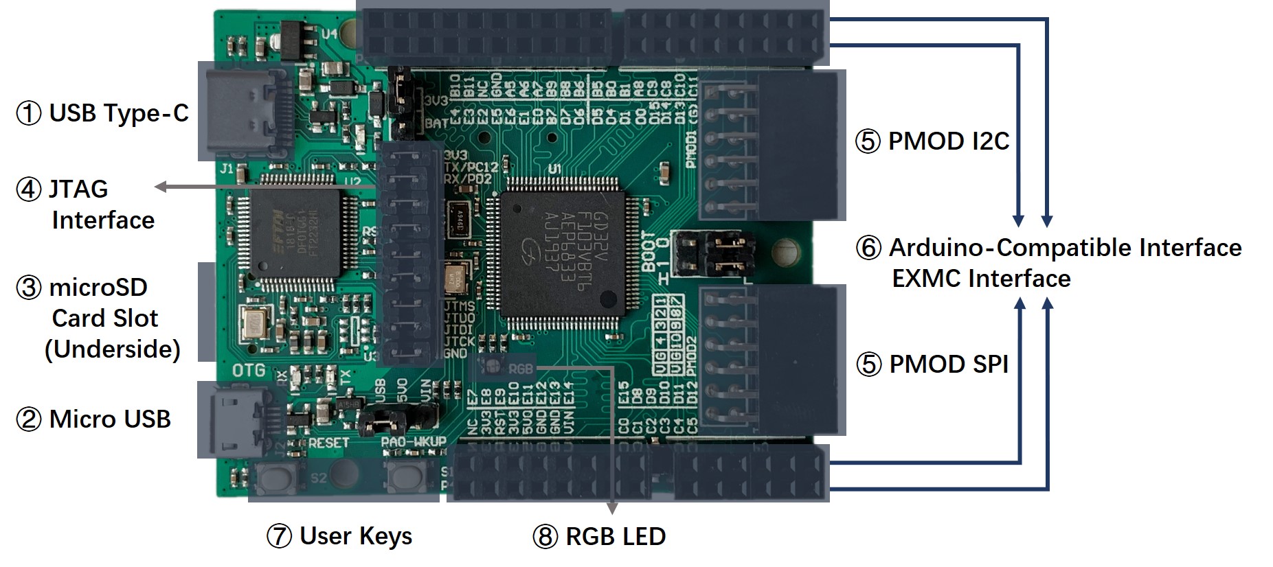
Fig. 2.1 RV-STAR Development Board
2.1.1. Features and Specifications
Microcontroller |
GD32VF103VBT6 (32-bit RISC-V Processor) |
||
Core |
Nuclei Bumblebee(RV32IMAC) |
||
Frequency |
108MHz |
||
Memory |
128KB Flash, 32KB SRAM |
||
Operating Voltage |
2.6 ~ 3.6V |
||
Peripheral |
Timer(Advanced 16-bit timer * 1, General 16-bit timer * 4) |
||
U(S)ART * 5, I2C * 2, SPI * 3, CAN * 2, USBFS * 1, EXMC * 1 |
|||
ADC * 2 (16 external channels), DAC * 2 |
|||
Power Supply |
5V USB or 5~9V External DC power (Arduino Vin) |
||
Dimensions |
66mm * 53.4mm |
||
On-board Devices
Extension Interface |
USB Type-C |
Download and debug, serial communication |
|
Micro USB |
USB OTG |
||
microSD card slot (not soldered by default) |
external SD card storage (SPI) |
||
JTAG Interface |
Separate MCU and debugger to make them work independently |
||
PMOD * 2 |
I2C, SPI |
||
Double row 2.54mm female header |
Arduino compatible (outside) |
||
EXMC (inside) |
|||
User Key * 2 |
Reset, Wakeup |
||
RGB LED * 1 |
|||
Note
RV-STAR Development Board supports multiple power supply inputs, it allows multiple power supply to be connected at the same time when the jumper is connected properly. About the jumper connection, please refer to Jumper Section.
The Micro USB port supports bi-directional power supply, and the default is input. In the case of using Micro USB as the single power supply, please pull down the VBUS_OE# signal (MCU PD3 pin) to fully turn on the MOSFET (Q1) to ensure good power supply.
2.1.2. Extension Interface
- Double row 2.54mm female header
The outside of P3~P6 is Arduino-Compatible interface, which can be directly connected to the relevant expansion boards with Arduino interface.
The corresponding MCU pins and function descriptions of the signals on the P3~P6 are listed below.
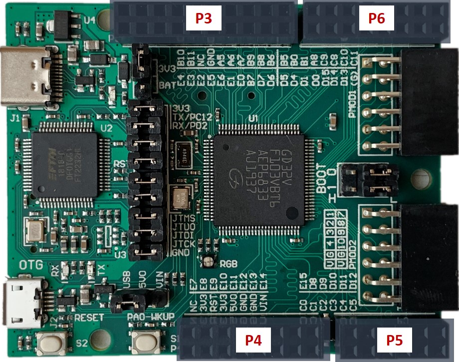
Fig. 2.2 Double row 2.54mm female header
Type |
Position |
Name |
MCU Pin |
Default Function |
Alternate Function |
Arduino |
2 |
PB10/SCL |
47 |
PB10 |
I2C1_SCL, USART2_TX, TIMER1_CH2 |
4 |
PB11/SDA |
48 |
PB11 |
I2C1_SDA, USART2_RX, TIMER1_CH3 |
|
6 |
NC |
/ |
/ |
/ |
|
8 |
GND |
/ |
GND |
/ |
|
10 |
PA5 |
30 |
PA5 |
SPI0_SCK, ADC01_IN5, DAC_OUT1 |
|
12 |
PA6 |
31 |
PA6 |
SPI0_MISO, ADC01_IN06, TIMER2_CH0, TIMER0_BRKIN |
|
14 |
PA7 |
32 |
PA7 |
SPI0_MOSI, ADC01_IN7, TIMER2_CH1, TIMER0_CH0_ON |
|
16 |
PB9 |
96 |
PB9 |
TIMER3_CH3, I2C0_SDA, CAN0_TX |
|
18 |
PB8 |
95 |
PB8 |
TIMER3_CH2, I2C0_SCL, CAN0_RX |
|
20 |
PB6 |
92 |
PB6 |
I2C0_SCL, TIMER3_CH0, USART0_TX, CAN1_TX |
|
EXMC |
1 |
EXMC_A20 |
3 |
PE4 |
EXMC_A20 |
3 |
EXMC_A19 |
2 |
PE3 |
EXMC_A19 |
|
5 |
EXMC_A23 |
1 |
PE2 |
EXMC_A23 |
|
7 |
EXMC_A21 |
4 |
PE5 |
EXMC_A21 |
|
9 |
EXMC_A22 |
5 |
PE6 |
EXMC_A22 |
|
11 |
EXMC_NBL1 |
98 |
PE1 |
EXMC_NBL1 |
|
13 |
EXMC_NBL0 |
97 |
PE0 |
TIMER3_ETI, EXMC_NBL0 |
|
15 |
EXMC_NADV |
93 |
PB7 |
I2C0_SDA, TIMER3_CH1, EXMC_NADV |
|
17 |
EXMC_NE0 |
88 |
PD7 |
EXMC_NE0, USART1_CK |
|
19 |
EXMC_NWAIT |
87 |
PD6 |
EXMC_NWAIT, USART1_RX |
Type |
Position |
Name |
MCU Pin |
Default Function |
Alternate Function |
Arduino |
2 |
VIN |
/ |
5~9V Power Supply |
/ |
4 |
GND |
/ |
GND |
/ |
|
6 |
GND |
/ |
GND |
/ |
|
8 |
5V0 |
/ |
5V0 Power Output |
/ |
|
10 |
3V3 |
/ |
3V3 Power Output |
/ |
|
12 |
NRST |
14 |
MCU Reset |
/ |
|
14 |
3V3 |
/ |
3V3 Power Output |
/ |
|
16 |
NC |
/ |
/ |
/ |
|
EXMC |
1 |
EXMC_D11 |
45 |
PE14 |
EXMC_D11, TIMER0_CH3 |
3 |
EXMC_D10 |
44 |
PE13 |
EXMC_D10, TIMER0_CH2 |
|
5 |
EXMC_D9 |
43 |
PE12 |
EXMC_D9, TIMER0_CH2_ON |
|
7 |
EXMC_D8 |
42 |
PE11 |
EXMC_D8, TIMER0_CH1 |
|
9 |
EXMC_D7 |
41 |
PE10 |
EXMC_D7, TIMER0_CH1_ON |
|
11 |
EXMC_D6 |
40 |
PE9 |
EXMC_D6, TIMER0_CH0 |
|
13 |
EXMC_D5 |
39 |
PE8 |
EXMC_D5, TIMER0_CH0_ON |
|
15 |
EXMC_D4 |
38 |
PE7 |
EXMC_D4, TIMER0_ETI |
Type |
Position |
Name |
MCU Pin |
Default Function |
Alternate Function |
Arduino |
2 |
PC5 |
34 |
PC5 |
ADC01_IN15 |
4 |
PC4 |
33 |
PC4 |
ADC01_IN14 |
|
6 |
PC3 |
18 |
PC3 |
ADC01_IN13 |
|
8 |
PC2 |
17 |
PC2 |
ADC01_IN12 |
|
10 |
PC1 |
16 |
PC1 |
ADC01_IN11 |
|
12 |
PC0 |
15 |
PC0 |
ADC01_IN10 |
|
EXMC |
1 |
EXMC_A17 |
59 |
PD12 |
EXMC_A17, TIMER3_CH0, USART2_RTS |
3 |
EXMC_A16 |
58 |
PD11 |
EXMC_A16, USART2_CTS |
|
5 |
EXMC_D15 |
57 |
PD10 |
EXMC_D15, USART2_CK |
|
7 |
EXMC_D14 |
56 |
PD9 |
EXMC_D14, USART2_RX |
|
9 |
EXMC_D13 |
55 |
PD8 |
EXMC_D13, USART2_TX |
|
11 |
EXMC_D12 |
46 |
PE15 |
EXMC_D12, TIMER0_BRKIN |
Type |
Position |
Name |
MCU Pin |
Default Function |
Alternate Function |
Arduino |
2 |
PB5 |
91 |
PB5 |
I2C0_SMBA, SPI2_MOSI, I2S2_SD, TIMER2_CH1, SPI0_MOSI, CAN1_RX |
4 |
PB0 |
35 |
PB0 |
ADC01_IN8, TIMER2_CH2, TIMER0_CH1_ON |
|
6 |
PB1 |
36 |
PB1 |
ADC01_IN9, TIMER2_CH3, TIMER0_CH2_ON |
|
8 |
PA8 |
67 |
PA8 |
USART0_CK, TIMER0_CH0, CK_OUT0, USBFS_SOF |
|
10 |
PC9 |
66 |
PC9 |
TIMER2_CH3 |
|
12 |
PC8 |
65 |
PC8 |
TIMER2_CH2 |
|
14 |
PC10 |
78 |
PC10 |
UART3_TX, USART2_TX, SPI2_SCK, I2S2_CK |
|
16 |
PC11 |
79 |
PC11 |
UART3_RX, USART2_RX, SPI2_MISO |
|
EXMC |
1 |
EXMC_NWE |
86 |
PD5 |
EXMC_NWE, USART1_TX |
3 |
EXMC_NOE |
85 |
PD4 |
EXMC_NOE, USART1_RTS |
|
5 |
EXMC_D3 |
82 |
PD1 |
EXMC_D3, CAN0_TX, OSCOUT |
|
7 |
EXMC_D2 |
81 |
PD0 |
EXMC_D2, CAN0_RX, OSCIN |
|
9 |
EXMC_D1 |
62 |
PD15 |
EXMC_D1, TIMER3_CH3 |
|
11 |
EXMC_D0 |
61 |
PD14 |
EXMC_D0, TIMER3_CH2 |
|
13 |
EXMC_A18 |
60 |
PD13 |
EXMC_A18, TIMER3_CH1 |
|
15 |
*GND |
/ |
*GND |
GND, R31(0 Ohm) needed |
- PMOD
The RV-STAR Development Board provides two sets of standard PMOD interfaces, which can be conveniently connected to the relevant expansion boards with PMOD interface.
The corresponding MCU pins and function descriptions of the signals on the PMOD1, PMOD2 are listed below.
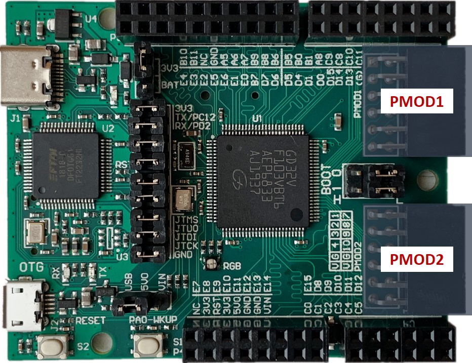
Fig. 2.3 PMOD
Type |
Position |
Name |
MCU Pin |
Default Function |
Alternate Function |
I2C |
1 |
PC7 |
64 |
PC7 |
I2S2_MCK, TIMER2_CH1 |
2 |
PC6 |
63 |
PC6 |
I2S1_MCK, TIMER2_CH0 |
|
3 |
PB10/SCL |
47 |
PB10 |
I2C1_SCL, USART2_TX, TIMER1_CH2 |
|
4 |
PB11/SDA |
48 |
PB11 |
I2C1_SDA, USART2_RX, TIMER1_CH3 |
|
5 |
GND |
/ |
GND |
/ |
|
6 |
3V3 |
/ |
3V3 Power Output |
/ |
|
7 |
PB4/NJTRST |
90 |
NJTRST |
SPI2_MISO, TIMER2_CH0, PB4, SPI0_MISO |
|
8 |
PB2/BOOT1 |
37 |
PB2/BOOT1 |
Can be used as GPIO after boot |
|
9 |
NC |
/ |
/ |
/ |
|
10 |
NC |
/ |
/ |
/ |
|
11 |
GND |
/ |
GND |
/ |
|
12 |
3V3 |
/ |
3V3 Power Output |
/ |
Type |
Position |
Name |
MCU Pin |
Default Function |
Alternate Function |
SPI |
1 |
PA4 |
29 |
PA4 |
SPI0_NSS, USART1_CK, ADC01_IN4, DAC_OUT0, SPI2_NSS, I2S2_WS |
2 |
SD_MOSI |
54 |
PB15 |
SPI1_MOSI, TIMER0_CH2_ON, I2S1_SD |
|
3 |
SD_MISO |
53 |
PB14 |
SPI1_MISO, USART2_RTS, TIMER0_CH1_ON |
|
4 |
SD_SCLK |
52 |
PB13 |
SPI1_SCK, USART2_CTS, TIMER0_CH0_ON, I2S1_CK, CAN1_TX |
|
5 |
GND |
/ |
GND |
/ |
|
6 |
3V3 |
/ |
3V3 Power Output |
/ |
|
7 |
SD_CS |
51 |
PB12 |
SPI1_NSS, I2C1_SMBA, USART2_CK, TIMER0_BRKIN, I2S1_WS, CAN1_RX |
|
8 |
PC13 |
7 |
PC13 |
TAMPER-RTC |
|
9 |
NC |
/ |
/ |
/ |
|
10 |
NC |
/ |
/ |
/ |
|
11 |
GND |
/ |
GND |
/ |
|
12 |
3V3 |
/ |
3V3 Power Output |
/ |
2.1.3. Jumper
The jumpers on RV-STAR are shown in the figure below, and their functions are described in the table below.
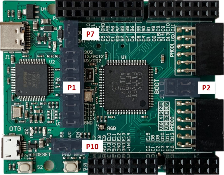
Fig. 2.4 Jumpers on RV-STAR
Jumper |
Description |
Options |
Default |
Function |
P1 |
GND |
2-1 |
O |
Used to connect debugger and MCU. Contains standard 4-wire JTAG and 2-wire UART interface. Disconnect here can separate MCU and debugger to make them work independently. (The debugger can be used to debug other devices, and the MCU can be debugged by other debuggers) |
JTAG-TCK |
4-3 |
O |
||
JTAG-TDI |
6-5 |
O |
||
JTAG-TDO |
8-7 |
O |
||
JTAG-TMS |
10-9 |
O |
||
Reset |
12-11 |
O |
||
UART-TX |
14-13 |
O |
||
UART-RX |
16-15 |
O |
||
VDE-3V3 |
18-17 |
O |
||
P2 |
BOOT0 (need to choose one) |
4-6 L |
O |
Boot from flash |
4-2 H |
If choose this, the boot mode depends on BOOT1’s value |
|||
BOOT1 |
3-5 L |
O |
If BOOT0=1, boot from Bootloader |
|
3-1 H |
If BOOT0=1, boot from SRAM |
|||
P7 |
RTC Power Supply (need to choose one) |
2-1 3V3 |
O |
From 3V3 power source on-board |
2-3 BAT |
From battery External Battery needed |
|||
P10 |
5V Power Source |
2-1 VIN |
From Arduino Vin port If choose this, Arduino Vin should be 5V0 |
|
2-3 VBUS |
O |
From USB Type-C |
Note
Symbol “O” in the up table means connected.
2.1.4. On-board Debugger Driver
- Install the Driver in Linux PC
For the Linux computer, the steps of installing driver for on-board debugger are as below:
Prepare the PC. Use the VMware WorkStation to have Linux virtual machine installed, or just use the native Linux OS on your computer. It is recommended to use Ubuntu 16.04 or above version.
Connect the PC and RV-STAR Development Board with the USB Type-C cable, make sure the USB is really be recognized by the Linux. For example, the USB symbol is highlighted in Ubuntu, as depicted in the figure below.
Use the command to check the USB status.
lsusb   // The example information displayed as below
...
Bus 001 Device 010: ID 0403:6010 Future Technology Devices International, Ltd FT2232xxxx
Use the following command to set udev rules, to make this USB can be accessed by plugdev group.
sudo vi /etc/udev/rules.d/99-openocd.rules
// Use vi command to edit the file, and add the following lines
SUBSYSTEM=="usb", ATTR{idVendor}=="0403",
ATTR{idProduct}=="6010", MODE="664", GROUP="plugdev"
SUBSYSTEM=="tty", ATTRS{idVendor}=="0403",
ATTRS{idProduct}=="6010", MODE="664", GROUP="plugdev"
Use the following command to check if this USB is belong to plugdev group.
ls /dev/ttyUSB*       // The example information showed as below after this command
/dev/ttyUSB0 /dev/ttyUSB1

ls -l /dev/ttyUSB1    // The example information showed as below after this command
crw-rw-r-- 1 root plugdev 188, 1 Nov 28 12:53 /dev/ttyUSB1
Add your user name into the plugdev group.
whoami
// Use above command to check your user name, assuming it is your_user_name
// Use below command to add your_user_name into plugdev group
sudo usermod -a -G plugdev your_user_name
Double check if your user name is really belong to plugdev group.
groups      // The example information showed as below after this command
... plugdev ...
// As long as you can see plugdev in groups, then means it is really belong to.
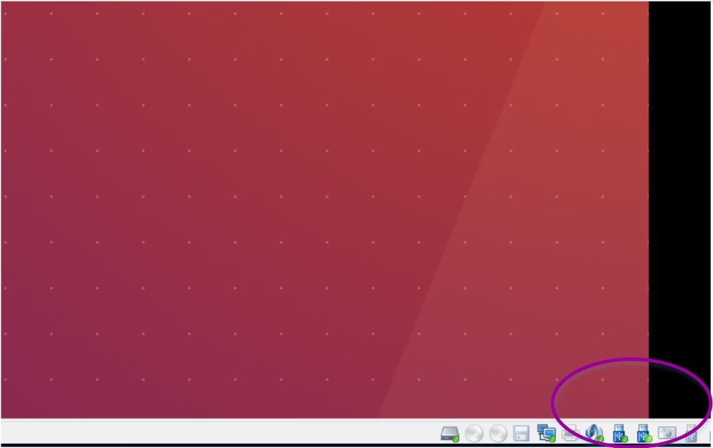
Fig. 2.5 Ubuntu OS recognized USB
- Install the Driver in Windows PC
For the Windows computer, the steps of installing driver for on-board debugger are as below:
Connect the PC and RV-STAR Development Board with the USB Type-C cable, make sure the USB is really be recognized by the Windows.
Download the on-board debugger’s Driver for Windows from this page, as depicted in the figure below.
After downloading the package, double-click the HBird_Driver.exe.
Since the on-board debugger has the functionality that “convert the UART to USB”, so if you have connected RV-STAR Development Board with PC and installed the driver successfully, then you will be able to see a USB Serial Port (e.g., COM8) show up in your Windows Device Manager.
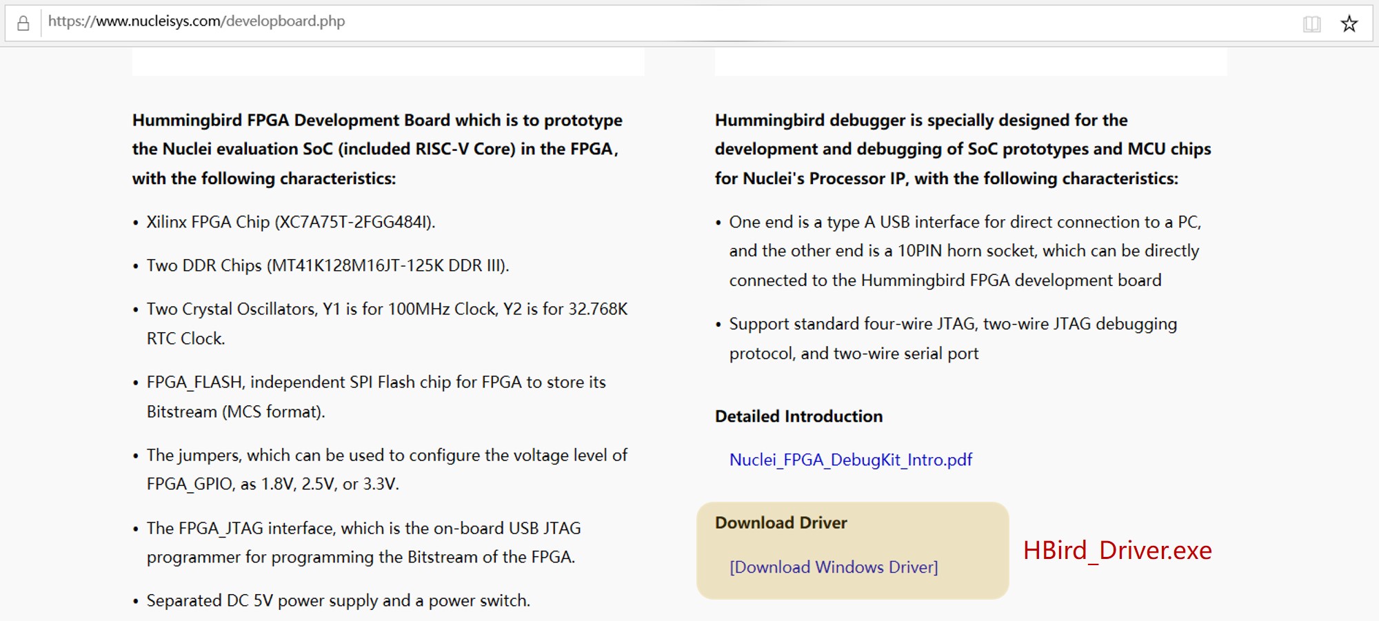
Fig. 2.6 Download the on-board debugger’s Driver for Windows
2.1.5. More Info
If you want to get more info about RV-STAR Development Board, GD32VF103 MCU and Nuclei Bumblebee Processor Core, please click the link in the following table to get the corresponding online docs.
Item |
Online Docs |
RV-STAR Development Board |
|
GD32VF103 MCU |
|
Nuclei Bumblebee Processor Core |