4.1.1.2. SoC Peripheral: Timer
Purpose
To get familar with the peripheral of GD32VF103 MCU: Timer
To know how to program peripheral registers to control the MCU Timer
Requirements
The following hardware and source codes are required:
PC host
Nuclei board (RV-STAR Development Board)
USB Type-C cable
nuclei-sdk/board-labs/rvstar/timer_pwm
Content
Through learning the Chapter 15 Timer of GD32VF103 MCU User Mannual to get familar with the usage of Timer.
Programming the Timer peripheral registers to generate PWM signals, and output these through pins which connected to RGB LED. Assigning the duty cycle of generated PWM signals to set the color of on-board RGB LED.
Principles
GD32VF103 MCU offers up to one 16-bit advanced timer (TIMER0), four 16-bit general timers(TIMERx=1,2,3,4), and two 16-bit basic timer (TIMER5 & TIMER6).
The advanced timer (TIMER0) can be seen as a three-phase PWM multiplexed on 6 channels. It has complementary PWM outputs with programmable dead-time generation. It can also be used as a complete general timer. The 4 independent channels can be used for input capture, output compare, PWM generation (edge-aligned or center-aligned counting modes), single pulse mode output. If configured as a general 16-bit timer, it can be synchronized with external signals or to interconnect with other general timers together which have the same architecture and features.
The general timer, known as TIMERx=1,2,3,4 can be used for a variety of purposes including general time, input signal pulse width measurement or output waveform generation such as a single pulse generation or PWM output, up to 4 independent channels for input capture/output compare. The general timer also supports an encoder interface with two inputs using quadrature decoder.
The basic timer, known as TIMER5 and TIMER6 are mainly used for DAC trigger generation. They can also be used as a simple 16-bit time base.
From the schematic of RV-STAR Development Board, we can see that PA1, PA2, PA3 are used to control RGB LED, and these pins can be used as TIMER1_CH1, TIMER1_CH2, TIMER1_CH3, so here we use TIMER1.
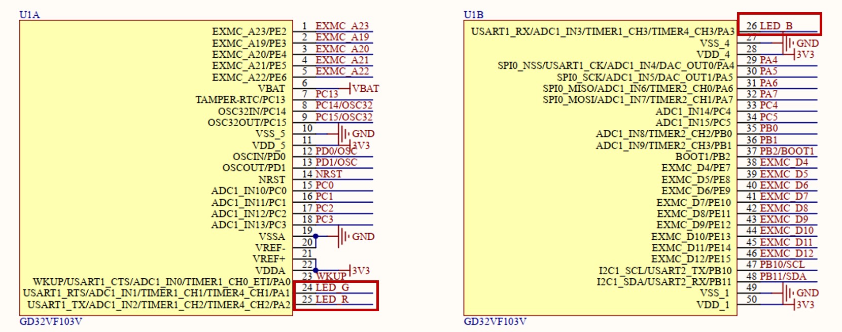
Fig. 4.5 Part of RV-STAR Development Board schematic
In Nuclei SDK, gd32vf103_gpio.h provides API to config the SoC GPIO, gd32vf103_timer.h provides API to operate the SoC Timer.
The code for this lab is located in nuclei-sdk/board-labs/rvstar/timer_pwm. You can see it in the appendix.
It can be divided into 3 parts:
Part1 : GPIO config, set PA1, PA2, PA3 to used as peripheral alternate function(TIMER1 CH1 CH2 CH3)
Part2 : Timer config, program TIMER1 to generate PWM signals
Part3 : RGB config, assign the duty cycle of generated PWM signals to set the color of on-board RGB LED
Steps
Connect RV-STAR Development Board and your computer with the USB Type-C cable.
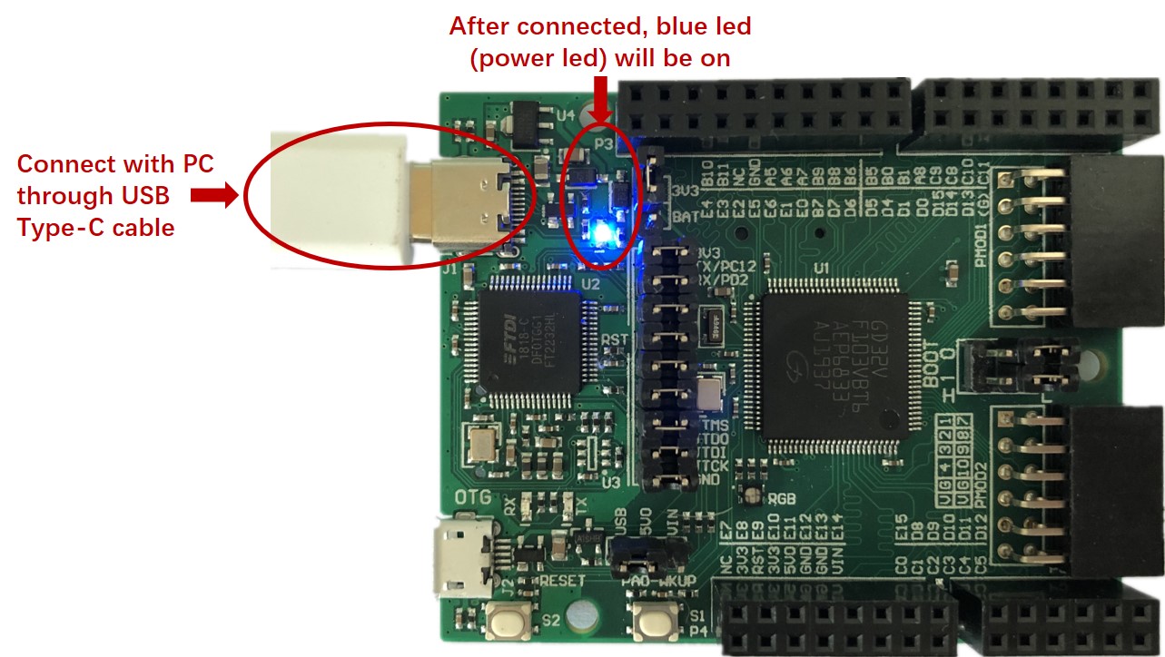
Fig. 4.6 Connect with PC
Note
When connect your board with the PC, just keep the on-board jumpers as default. About on-board jumpers’ function, please refer to Jumper Section.
Compile and run the
nuclei-sdk/board-labs/rvstar/timer_pwmexample. About the develop environment, you can choose Nuclei SDK or Segger Embedded Studio.
Nuclei SDK
Using the following commands:
cd /nuclei-sdk/board-labs/rvstar/timer_pwm
make SOC=gd32vf103 BOARD=gd32vf103v_rvstar upload
Note
About the acquisition of source codes, please refer to Software Source Codes.
About the detailed usage of Nuclei SDK, please refer to How to develop with Nuclei SDK.
Segger Embedded Studio
Using the following actions:
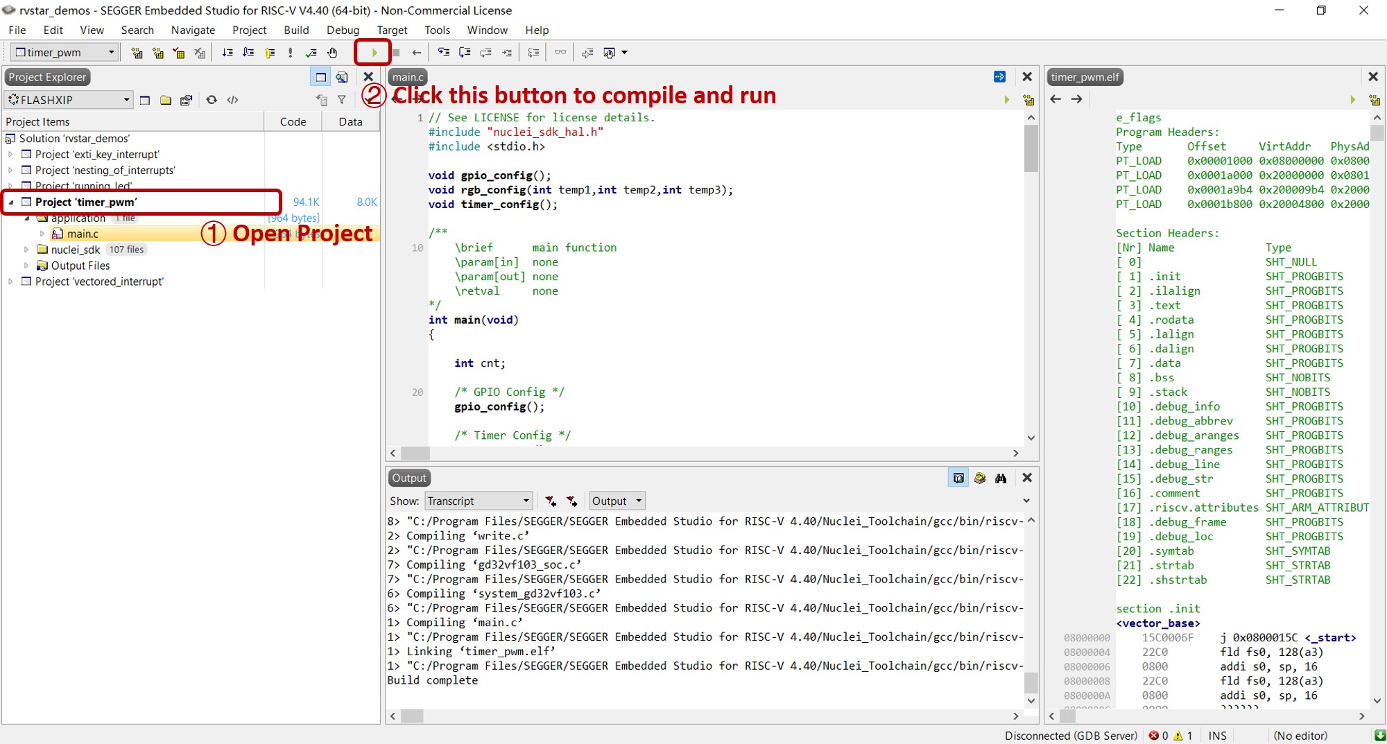
Fig. 4.7 Operations in Embedded Studio
Note
About the acquisition of Segger Embedded Studio solutions, please refer to Software Source Codes.
About the detailed usage of Segger Embedded Studio, please refer to How to develop with Segger Embedded Studio.
Check the color change of on-board RGB LED.
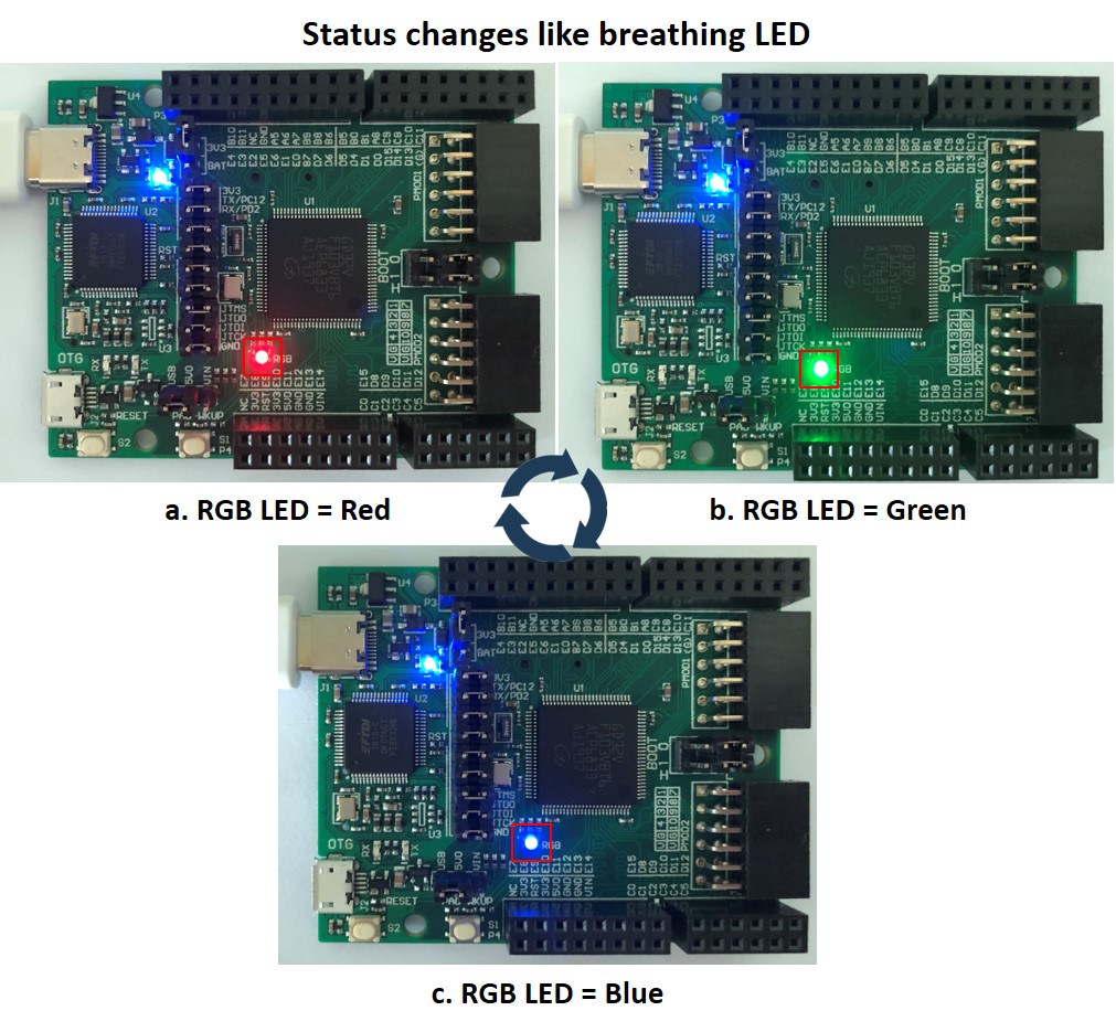
Fig. 4.8 Experimental results
Exercises
Try to create you own application which using TIMER4 to generate PWM signals to control on-board RGB LED.
Appendix
rvstar/timer_pwm/main.c
/**
    \brief      main function
    \param[in]  none
    \param[out] none
    \retval     none
*/
int main(void)
{

    int cnt;

    /* GPIO Config */
    gpio_config();

    /* Timer Config */
    timer_config();

    while(1)
    {
      /* set rgb_led status */

        for(cnt = 255; cnt >=0; cnt--)
        {
          rgb_config(cnt, 0, 0);
          delay_1ms(5);
        }
        for(cnt = 255; cnt >=0; cnt--)
        {
          rgb_config(0, cnt, 0);
          delay_1ms(5);
        }
        for(cnt = 255; cnt >=0; cnt--)
        {
          rgb_config(0, 0, cnt);
          delay_1ms(5);
        }
    }

    return 0;
}

/**
    \brief      configure the GPIO ports
    \param[in]  none
    \param[out] none
    \retval     none
*/
void gpio_config()
{
    rcu_periph_clock_enable(RCU_GPIOA);
    rcu_periph_clock_enable(RCU_AF);

    /*Configure PA1 PA2 PA3(TIMER1 CH1 CH2 CH3) as alternate function*/
    gpio_init(GPIOA, GPIO_MODE_AF_PP, GPIO_OSPEED_50MHZ, LEDG_PIN);
    gpio_init(GPIOA, GPIO_MODE_AF_PP, GPIO_OSPEED_50MHZ, LEDR_PIN);
    gpio_init(GPIOA, GPIO_MODE_AF_PP, GPIO_OSPEED_50MHZ, LEDB_PIN);
}

/**
    \brief      configure the TIMER peripheral
    \param[in]  none
    \param[out] none
    \retval     none
*/
void timer_config()
{

   timer_oc_parameter_struct timer_ocinitpara;
   timer_parameter_struct timer_initpara;

   rcu_periph_clock_enable(RCU_TIMER1);

   timer_deinit(TIMER1);
   /* initialize TIMER init parameter struct */
   timer_struct_para_init(&timer_initpara);
   /* TIMER1 configuration */
   timer_initpara.prescaler         = 107;
   timer_initpara.alignedmode       = TIMER_COUNTER_EDGE;
   timer_initpara.counterdirection  = TIMER_COUNTER_UP;
   timer_initpara.period            = 254;
   timer_initpara.clockdivision     = TIMER_CKDIV_DIV1;
   timer_initpara.repetitioncounter = 0;
   timer_init(TIMER1, &timer_initpara);

   /* initialize TIMER channel output parameter struct */
   timer_channel_output_struct_para_init(&timer_ocinitpara);
   /* CH0, CH1 and CH2 configuration in PWM mode */
   timer_ocinitpara.outputstate  = TIMER_CCX_ENABLE;
   timer_ocinitpara.outputnstate = TIMER_CCXN_DISABLE;
   timer_ocinitpara.ocpolarity   = TIMER_OC_POLARITY_HIGH;
   timer_ocinitpara.ocnpolarity  = TIMER_OCN_POLARITY_HIGH;
   timer_ocinitpara.ocidlestate  = TIMER_OC_IDLE_STATE_LOW;
   timer_ocinitpara.ocnidlestate = TIMER_OCN_IDLE_STATE_LOW;

   timer_channel_output_config(TIMER1,TIMER_CH_1,&timer_ocinitpara);
   timer_channel_output_config(TIMER1,TIMER_CH_2,&timer_ocinitpara);
   timer_channel_output_config(TIMER1,TIMER_CH_3,&timer_ocinitpara);


   /* CH1 configuration in PWM mode0 */
   timer_channel_output_pulse_value_config(TIMER1,TIMER_CH_1,255);
   timer_channel_output_mode_config(TIMER1,TIMER_CH_1,TIMER_OC_MODE_PWM0);
   timer_channel_output_shadow_config(TIMER1,TIMER_CH_1,TIMER_OC_SHADOW_DISABLE);

   /* CH2 configuration in PWM mode0 */
   timer_channel_output_pulse_value_config(TIMER1,TIMER_CH_2,255);
   timer_channel_output_mode_config(TIMER1,TIMER_CH_2,TIMER_OC_MODE_PWM0);
   timer_channel_output_shadow_config(TIMER1,TIMER_CH_2,TIMER_OC_SHADOW_DISABLE);

   /* CH3 configuration in PWM mode0 */
   timer_channel_output_pulse_value_config(TIMER1,TIMER_CH_3,255);
   timer_channel_output_mode_config(TIMER1,TIMER_CH_3,TIMER_OC_MODE_PWM0);
   timer_channel_output_shadow_config(TIMER1,TIMER_CH_3,TIMER_OC_SHADOW_DISABLE);

   /* auto-reload preload enable */
   timer_auto_reload_shadow_enable(TIMER1);
   /* auto-reload preload enable */
   timer_enable(TIMER1);
}

/**
    \brief      configure the rgb_led
    \param[in]  temp1:set value of red channel between 0 to 255
    \param[in]  temp2:set value of green channel between 0 to 255
    \param[in]  temp3:set value of blue channel between 0 to 255
    \param[out] none
    \retval     none
*/
void rgb_config(int temp1,int temp2,int temp3)
{
   /* CH1 duty cycle set */
   timer_channel_output_pulse_value_config(TIMER1,TIMER_CH_1,(255-temp2));

   /* CH2 duty cycle set */
   timer_channel_output_pulse_value_config(TIMER1,TIMER_CH_2,(255-temp1));

   /* CH3 duty cycle set */
   timer_channel_output_pulse_value_config(TIMER1,TIMER_CH_3,(255-temp3));
}